

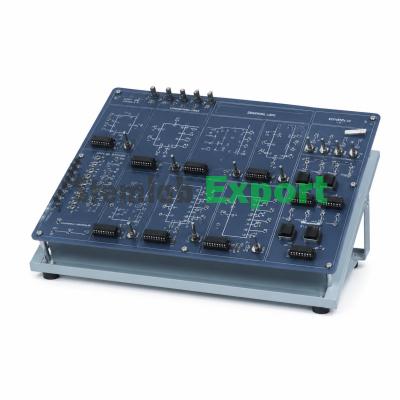
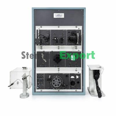
Tachometer Test Module Deluxe
Product Overview
Tachometer Test Module, to teach linear and angular speed measurement techniques. In this module placed on the upper part we have a miniature motor used to move the axle.
Technical Specifications
ATENG 12370 � Tachometer Test Module
- Voltage to frequency (V/F) converter:
- Transfer ratio: 1 kHz/V.
This unit is common for the different test modules type �ATENG 12356�
- Maximum input frequency: 10 kHz.
and can work with one or several modules.
- No linearity: 0.024 %.
All elements are included in a metallic box.
- Other circuits:
- Signal conditioning circuits:
Full-wave rectifier.
- Amplifiers:
- 40 kHz oscillator:
- DC amplifiers:
- Output frequency: 41093 Hz.
- Three amplifiers.
- Output amplitude: 5 Vpp.
- Input range: +/-12 VDC.
- Alarm oscillator:
- Input impedance: 100 K?.
- Oscillator frequency: 700 Hz.
- Adjustable gain: 1, 10,100 for the �Amplifier 1� and
- Switch turn off voltage: 2.3 V.
�Amplifier 2�.
- Electronic switch:
- Fixed gain: 100 for �x100 Amp�.
- Input voltage: 12 V max.
- AC amplifier:
- Switch voltage: 2.1 V.
- Input range: 12 VAC.
- Output current: 500 mA max.
- Adjustable gain: 10, 100,1000.
- Control circuits:
- Bandwidth: 10 - 16000 Hz.
- PID:
- Power amplifier:
Process control applications.
- Input range: 12 V max.
Independent PID parameters adjustment (Proportional
- Output current: 1.5 A max.
Integrative and Derivative ).
- Output power: 9 W max.
- Industrial controller:
- Current amplifier:
- Input: DC voltage, RTD sensor or thermocouple.
- Gain: 10,000.
- Output 1: Relay.
- Output current: 1 A max.
- Alarm output: Relay.
- Buffers:
- Relay:
- Two buffers.
Double relay.
- Input voltage: 12 V max.
NO and NC terminal.
- Input impedance: 100 K?.
- 12 VDC coil excitation.
- Inverting amplifier:
- DC dimmer:
- Input voltage: 12 V max.
Light dimmer or DC motor speed controller applications.
- Input impedance: 100 K?.
PWM generator.
- Gain: -1.
Frequency and duty cycle adjustable.
- Differential amplifier:
- Power elements:
- Input voltage: 12 V max.
- Power supply:
- Inputs impedance: 100 K? (Input A) and 200 K? (Input B).
- AC voltage range: 0 � 30 VAC.
- A (Differential gain): 1.0.
- d DC voltage range: 0 �15 VDC.
- A (Common mode gain): 0.02 max.
- c Output current: 4 A max.
- Instrumentation amplifier:
- DC Source:
- Input voltage: 12V max.
Two output for each voltage.
- Inputs impedance: 100 K?.
- DC voltages:+5 VDC, -5 VDC,+12 VDC, -12 VDC, 0 to 12 Var.
- A (Differential gain): 1.0.
- d Output current: 500 mA max.
- A (Common mode gain): 0.006 max.
- c � Wave Generator:
- Summing amplifier:
Sine, square, triangular and sawtooth waveforms.
- Input voltage: 12 V max.
- Frequency range: 100 to 10000 Hz.
- Three inputs.
- Amplitude range: Adjustable +/- 10V.
- Gain: 1.
- Potentiometers:
- Comparators:
Four potentiometers.
Schmitt trigger.
- Impedance values: 0-1 K?, 0-5 K?, 0-10 K? and 0-20 K?.
- Filters:
- Power dissipation: 1 W max.
- 40kHz filter: Pass-band filter at 40 kHz.
- Measuring elements:
- Low-pass filter: selectable cut-off frequencies at 15 Hz
- L.E.D. bargraph display:
1.44 Hz, 0.14 Hz.
- Input range: 0-5 V.
- Integrator:
- Counter/Timer:
- Selectable time constants: 100 ms, 1 s, 10 s.
Temporization applications.
- Differentiator:
Counting applications.
- Selectable time constants: 10 ms,100 ms, 1 s.
- Moving coil meter.
- �Sample/Hold� circuit:
- Analog inputs and outputs:
- Time constant: 1 ms.
- Two analog outputs:
- Converters circuits:
- Output voltage range: -10 V to +10 V.
- Voltage to current (V/I) converter:
- Four analog inputs:
- Output current: �20 mA max.
- Input voltage range: -10 V to +10 V.
- Transfer ratio: 10 mA/V.
- Computer Control System (SCADA):
- Current to voltage (I/V) converter:
- Control Interface, integrated in the box of the base unit (ATENG 12358).
- Output voltage: �2 V (6 V max.).
- Data acquisition board to be installed in a computer slot.
- Transfer ratio: 0.1 V/mA.
- Computer Control Software.
- Frequency to voltage (F/V) converter:
Cables and Accessories, for normal operation.
- Transfer ratio: 1 V/kHz. Manuals: It is supplied with the following: Required Services
- Maximum input frequency: 10 kHz. Assembly and Installation, Interface and Software
- No linearity: 0.024 %. Starting-up, Safety, Maintenance & Practices
Tachometer Test Module Deluxe Related Products
Other specialized products for engineering, technical educational and scientific laboratories such as Tachometer Test Module Deluxe.


Buy Tachometer Test Module Deluxe from India's Trusted Manufacturer
Stemlab Export is a leading manufacturer and exporter of laboratory and scientific equipment in India, supplying institutions and bulk tenders worldwide — with direct factory pricing, recognised standards and global exports.
Direct from Factory
No middlemen — manufacturer pricing, full quality control and quick quotations on every product.
Standards Compliant
Built to recognised standards such as ASTM, IS and BIS where applicable, accepted by institutions and tenders.
Bulk & Tender Quantities
Supplied in bulk volumes to procurement bodies, education ministries and global tenders.
Worldwide Shipping
Exports to 30+ countries with complete documentation and logistics handled in-house.
Who Uses Our Tachometer Test Module Deluxe?
Our Tachometer Test Module Deluxe is engineered for teaching laboratories, research facilities, government projects and international export contracts. Every unit ships with quality documentation, standards compliance and dependable after-sales support.
Institutions choose Stemlab Export for transparent pricing, on-time delivery and decades of manufacturing experience across hundreds of scientific, educational and engineering products — from school science labs to advanced research benches.
Bulk Order of Tachometer Test Module Deluxe?
Send us your requirement list or tender BOQ and we'll respond with a fully compliant manufacturer quote. Trusted by institutional and government buyers worldwide.